
Small-size Gasoline Engine Fuel System
An engine really runs primarily on air, about 14 parts of air to one of gasoline. The job of the fuel system, therefore, is to first mix, air and fuel in proper proportions and then deliver it to the combustion chamber. The carburetor is the key component. It mixes the fuel and air, and in some small engines, it also houses the fuel pump, which draws fuel from the tank and delivers it to the carburetor.
The typical small engine carburetor is of simple design, simple that is, if you’re used to automotive carburetors. If you were able to wade your way through engine and ignition system operation, however, you can understand carburetion too.
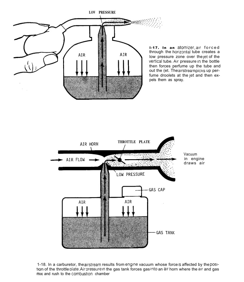
Begin by thinking of a perfume atomizer. You squeeze the bulb and a spray of perfume comes out. If the bowl contained gasoline, you’d get a spray mixture of air and gasoline droplets. The atomizer looks simple, but you probably never thought about how it works, so as a fringe benefit of learning about small gas engines, you can also understand this boudoir essential.
With the atomizer, squeezing the bulb forces air through a horizontal tube, shown in 1-17. This creates a low-pressure zone over a jet of a connecting tube that extends down into the perfume. Since the air in the atomizer bottle itself is at normal air pressure (14.7 pounds per square inch at sea level, a bit less at higher altitudes), it forces the perfume up the tube toward the lower pressure. Then the air stream picks up the droplets and expels them as spray.
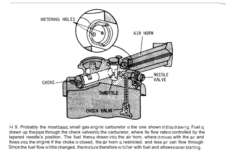
This is really what a carburetor is all about. But instead of perfume, its jet carries gasoline. Instead of blowing air past the tip of the jet by means of a bulb, the carburetor has a specially-shaped cylinder called an air horn through which the engine applies vacuum, as in 1-18.
The two-cycle engine uses vacuum created in the crankcase when the piston rises. That vacuum pulls open the reed valve and draws in air from the carburetor air horn to create a low-pressure area there. As outside air rushes in to fill the vacuum, it creates a special little low-pressure zone around the tip of the jet, drawing fuel out in the form of droplets that it
Carries into the Crankcase
The four-cycle engine uses vacuum created in the cylinder when the piston goes down. Instead of flowing into the crankcase, the air-fuel mixture goes directly into the cylinder when the intake valve opens. Aside from these differences, the method of supplying fuel to these two engines is essentially the same. The air flow through the carburetor determines the amount of air-fuel mixture the engine will receive. To control that flow, there is a circular plate called the throttle, which is hinged in the center of the air horn.
When you operate the throttle control (or step on the gas pedal in a car) you pivot the circular plate to the vertical position to permit maximum air-fuel mixture flow.
It’s also important to understand how the fuel gets to the carburetor and how it is metered into the jet. For the little mechanisms that do these jobs are the key moving parts in the carburetor and are subject to failure. These parts must function properly, or else either of two problems will occur:
1)Too little fuel will get into the cylinder, and the engine will starve and stall.
2) Or too much fuel will get in, causing the engine to flood and then stall. (The right amount for an explosive mixture is in a narrow range.)
The fuel tank houses the gasoline. And in the simplest setups it is mounted above the carburetor and connected to it by a tube. Fuel flows by gravity from tank to carburetor, which has a small bowl to store enough to keep the engine supplied for perhaps a minute. This system works fine for household-type mowers and blowers.
Another basic design, perhaps the simplest, is the suction lift carburetor, shown in 1-19. This carburetor consists of a jet, an adjustable tapered needle that threads into it (to adjust fuel flow), a throttle, a choke, an air horn, and one or two suction pipes (“fuel ‘drinking straws”) that project down into the gas tank. The vacuum in the carburetor air horn sucks fuel up the straw through the jet into the air horn.
In many mowers and blowers, however, gravity feed isn’t possible because the gas tank can’t be mounted high enough, and the simple suction lift doesn’t provide the fuel control to enable the engine to function well at all speeds, In these cases more complex fuel pumping and metering systems are used. These are both built into the carburetors on the small engines you are likely to have 011 your mower or blower. In the chain saw, clearly, the varied working angles make a gravity feed system impractical. And to provide good fuel supply under all conditions, the simple suction lift wouldn’t be much good either.
The on-carburetor pump is a piece of flexible plastic into which are cut two C-shaped Haps that move up and down in response to pulses of vacuum in the engine. They cover and uncover passages from the fuel tank and to the carburetor’s fuel delivery system, where fuel is metered into the air horn. In some carburetors, the crankcase pressure and vacuum simply move a one-piece diaphragm, which draws open and forces closed inlet and outlet ball-type valve. This design consists of a steel ball in a specially-shaped fit-ting threaded into the passage. When the ball is moved one way; it seals the passage; when it is moved the other way, fuel can How past it.
Once the fuel is in the carburetor, either of two methods is used to con trol the storage and metering. On most mowers and blowers, a float system is used, much like the one listed in a toilet tank. As shown in l-20, a hinged Hoat with a projecting arm drops when the fuel level in the carburetor bowl is low, permitting a tapered needle to come off its seat, opening a passage to the bowl. The fuel How’s in, causing the Heat to rise. When the Hoat reaches a designated level, it pushes the needle back into its seat, shutting off the fuel How. The Hoat insures an adequate supply and the jet draws from the Hoat bowl asnecessary.
On chain saws the Hoat systenl won’t work, because the chain saw is used at so many different angles that the Hoat wouldn’t keep the bowl properly filled at all times. Instead, there are Hoatless designs in use, featuring a diaphragm that moves a tapered needle valve. When the crankcase creates a vacmmi, it draws the carburetor diaphragm; this creates a vacuum that also draws the needle off its seat, permitting fuel to How through a jet into the air horn, to mix with the inrushing air. As shown in l-21, diaphragms may work in many ways. Also see l-22 through l-25.
Post time: Jan-11-2023